MAE3 Product Description
The MAE3 IS NOT RECOMMENDED FOR NEW PROJECTS
Please discover our New Redesigned MAE4
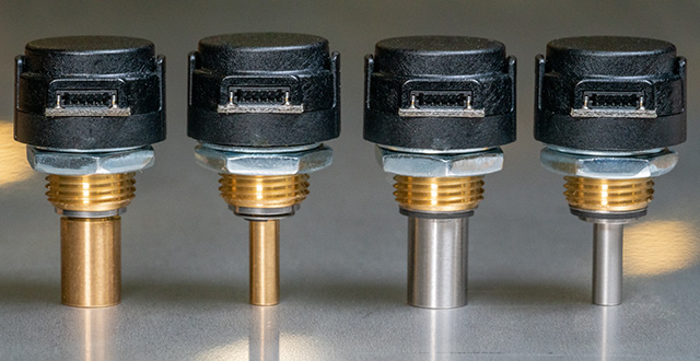
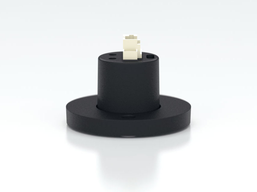
The MAE3 is an absolute magnetic kit encoder that provides shaft position information over 360° of rotation with no stops or gaps. This magnetic encoder is designed to easily mount to, and dismount from, an existing shaft to provide digital feedback information. The MAE3 is available with an analog or a pulse width modulated (PWM) digital output.
Analog output provides an analog voltage that is proportional to the absolute shaft position. Analog output is only available in 10-bit resolution.
PWM output provides a pulse width duty cycle that is proportional to the absolute shaft position. PWM output is available in 10-bit and 12-bit resolutions. While the accuracy is the same for both encoders, the 12-bit version provides a higher resolution.
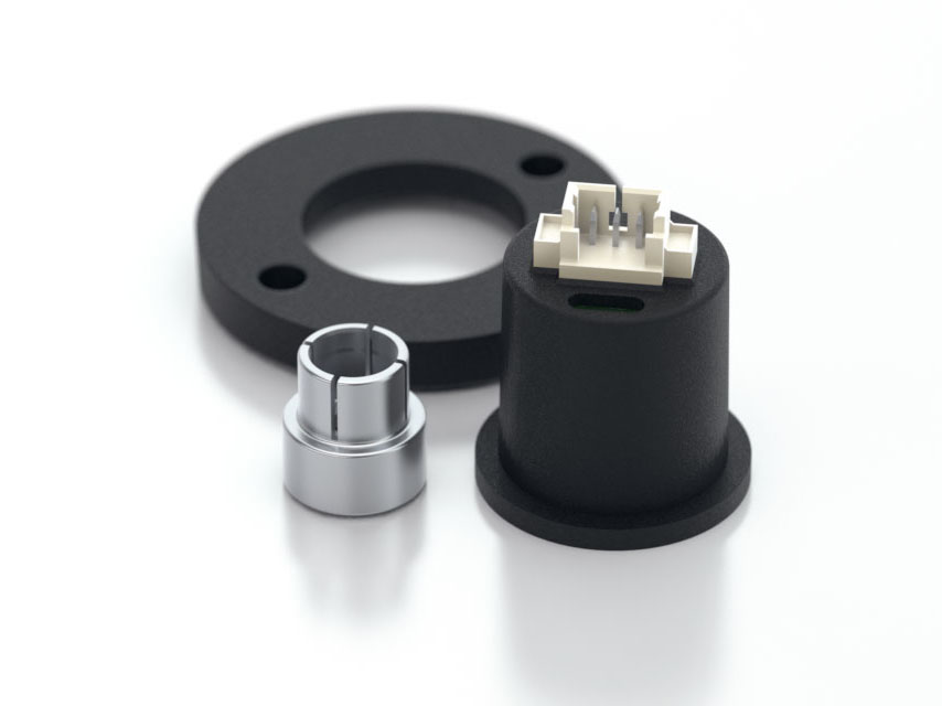
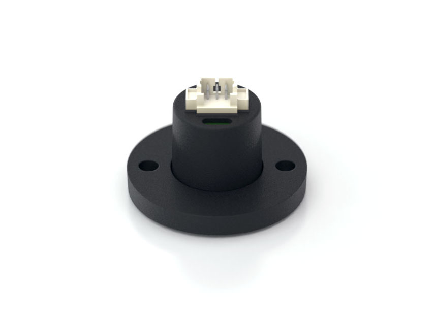
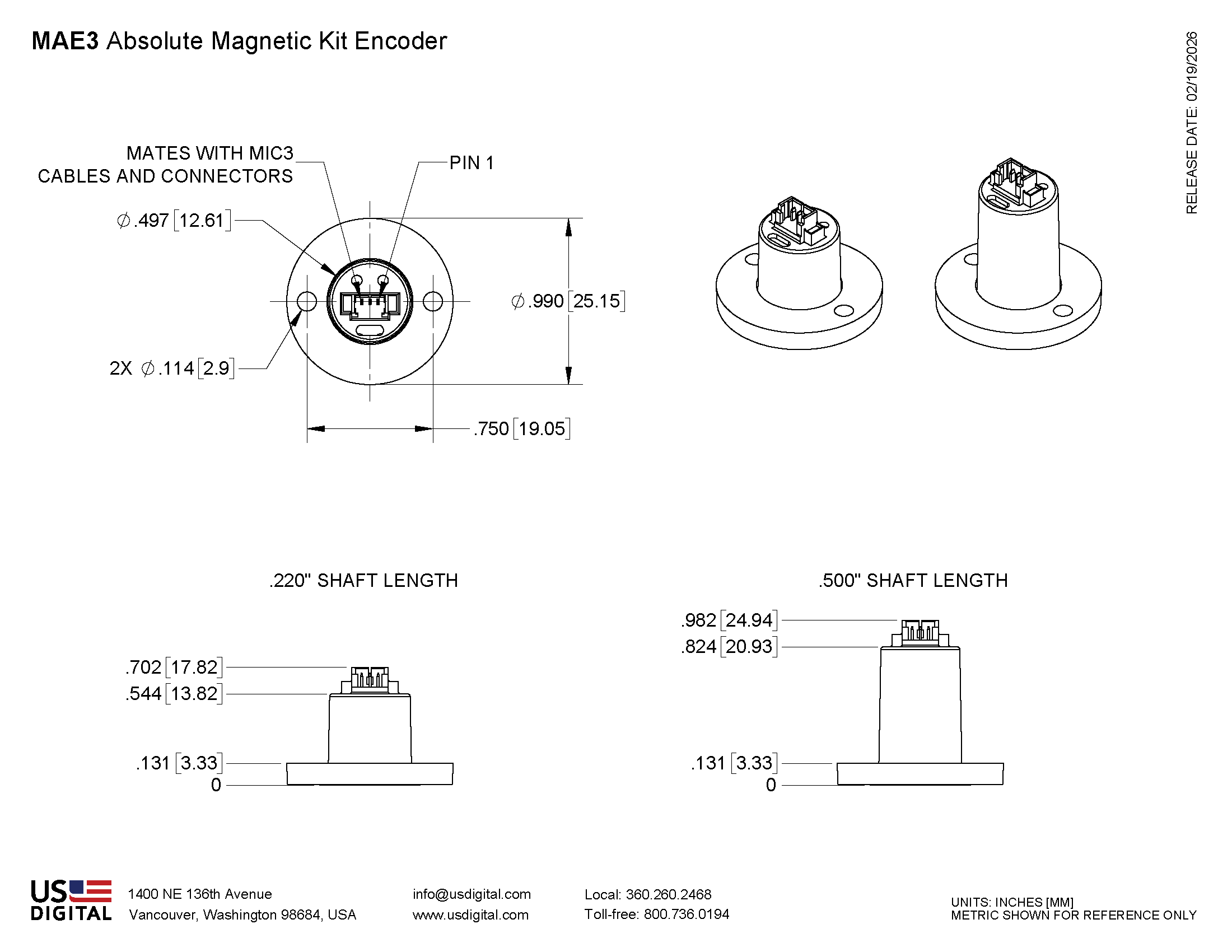
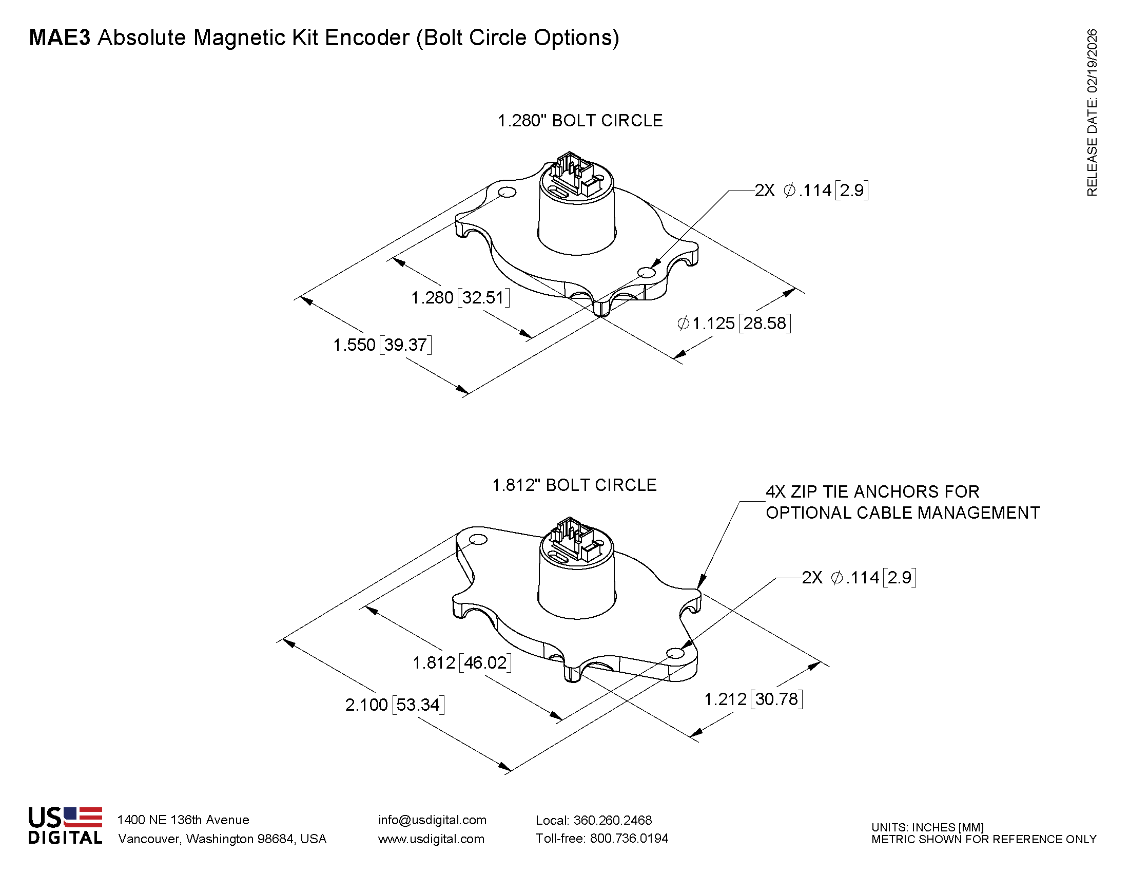
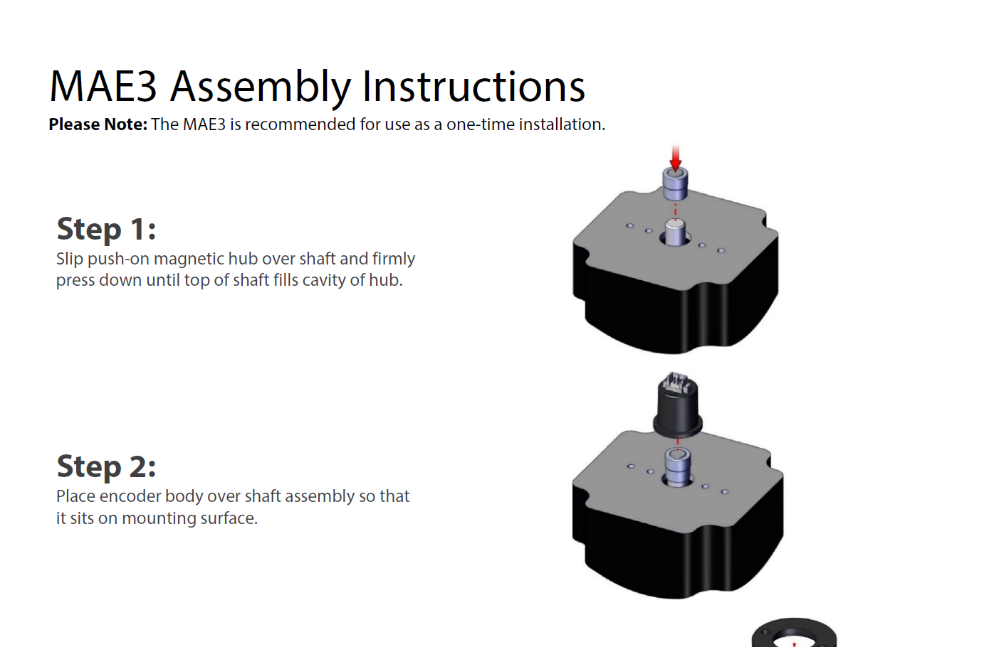
The MAE3 consists of three components: base, push-on magnetic hub, and encoder body. The base will accommodate 0.750 in., 1.280 in., and 1.812 in. mounting bolt circles. No tools are needed for the push-on, collet gripping hub. The hub mounts to a standard shaft in seconds and provides a simple and reliable means of securing the magnet to the shaft.
Two 4-40 pan head screws secure the base and encoder body to any flat surface. If desired, the encoder can be powered up and rotated by hand to any desired absolute position before the screws are tightened.
Connecting to the MAE3 is simple. The 3-pin, high retention, snap-in 1.25mm pitch polarized connector provides for +5V, output, and ground.
Product Specifications
ENVIRONMENTAL
PARAMETER
VALUE
UNITS
Operating Temperature
-40 to +125
C
Vibration (5Hz to 2kHz)
20
G
Electrostatic Discharge, Human Body Model
± 2
kV
MECHANICAL
PARAMETER
VALUE
UNITS
Max. Shaft Axial Play
±0.025
in.
Max. Shaft Runout (1)
0.004 T.I.R.
in.
Max. Acceleration
250000
rad/sec²
Max. Hub Moment of Inertia
9.42 x 10^-7
oz-in-s²
Mounting Screw Size
#4-40 x 1/4
in.
2 Screw Bolt Circle Diameter
0.750 ± 0.005
in.
2 Screw Bolt Circle Diameter
1.280 ± 0.005
in.
2 Screw Bolt Circle Diameter
1.812 ± 0.005
in.
Required Shaft Length, including axial play (1)
Mounting Screw Torque
4 - 6
in-lbs
Technical Bulletin TB1001 - Shaft and Bore Tolerances
Download
(1) For optimum accuracy, the magnetic hub must be fully seated on the shaft and the shaft play must meet the specified axial and radial limits.
(2) The chip that decodes position uses sampled data. There will be fewer readings per revolution as the speed increases. The formula for the number of readings per revolution is given by:
10-bit PWM:
n = 625200 / rpm
12-bit PWM / Analog:
n = 156600 / rpm
ELECTRICAL
PARAMETER
MIN.
TYP.
MAX.
UNITS
Power Supply
4.5
5.0
5.5
Volts
Supply Current
16
20
mA
Power-up Time
50
mS
ANALOG OUTPUT OPERATION
Analog output is only available in 10-bit resolution. The analog output voltage is ratiometric to the power supply voltage and will typically swing within 15 millivolts of the power supply rails with no output load. This non-linearity near the rails increases with increasing output loads. For this reason, the output load impedance should be ≥4.7kΩ and less than 100pF. The graphs below show the typical output levels for various output loads when powered by a 5V supply.
PARAMETER
MIN.
TYP.
MAX.
UNITS
Position Sampling Rate
2.35
2.61
2.87
kHz
Propagation Delay
384
μS
Analog Output Voltage Maximum (1)
4.987
Volts
Analog Output Voltage Minimum (1)
0.015
Volts
Output Short Circuit Sink Current (2)
32
50
mA
Output Short Circuit Source Current (2)
36
66
mA
Output Noise (1-σ limit)
0.046
Deg. RMS
(1) With no output load. See graphs below.
PWM OUTPUT OPERATION
The magnetic sensor chip in the MAE3 has an on-chip RC oscillator which is factory trimmed to 5% accuracy at room temperature (10% over full temperature range). This tolerance influences the sampling rate and the pulse period of the PWM output. If only the PWM pulse width ton and nominal pulse period are used to measure the angle, the resulting value also has this timing tolerance. However, this tolerance can be canceled by measuring both ton and toff and calculating the angle from the duty cycle.
PARAMETER
MIN.
TYP.
MAX.
UNITS
PWM Frequency (-40C to 125C)
Minimum Pulse Width
Maximum Pulse Width
Internal Sampling Rate
Propagation Delay
Output Transition Noise, 12-bit version (1)
.03
Deg. RMS
Output Transition Noise, 10-bit version (1)
.12
Deg. RMS
Output High Voltage (VOH : @4mA Source) (2)
Vcc -0.5
V
Output Low Voltage (VOL : @4mA Sink) (2)
0.4
V
(1) Transition noise is the jitter in the transition between two adjacent position steps.
10-bit PWM:
x = ((t on * 1026) / (t on + t off )) -1
If x <= 1022, then Position = x
If x = 1024 then Position = 1023
12-bit PWM:
x = ((t on * 4098) / (t on + t off )) -1
If x <= 4094, then Position = x
If x = 4096 then Position = 4095
PIN-OUTS
ANALOG OUTPUT (MAE3-A):
PIN
NAME
DESCRIPTION
1
5
+5VDC power
2
A
Analog output
3
G
Ground
PWM OUTPUT (MAE3-P10, MAE3-P12):
PIN
NAME
DESCRIPTION
1
5
+5VDC power
2
P
PWM output
3
G
Ground
ACCESSORIES
SCREWS
Part #:
SCREW-440-250-PH
Description:
4-40 x 1/4" Pan head screw
Quantity Required for Mounting
2 per encoder
CABLES / CONNECTORS
3-PIN MICRO:
Connector built into encoder: Molex# 53398-0371.
Mating connector housing: Molex# 51021-0300.
Mating connector individual crimp-on pins: Molex# 50079-8100.
To install connector pins, a special crimp tool is needed: Molex# 50079.
PRODUCT CHANGE NOTIFICATIONS
Title
Date
Description
Download
Hub End of Life - PCN 5549
12/15/2015
This PCN is a formal notification that US Digital is discontinuing the following bore sizes for the MAE3 product line: .079 (2mm), .091 (2.3mm), .098 (2.5mm), .156 (5/32").
Download
Additional Information
Product Notes
Cables and connectors are not included and must be ordered separately.
US Digital® warrants its products against defects in materials and workmanship for two years. See complete warranty for details.
Assembly Instructions & Videos
Related
3D Model Downloads
Please
configure your product first
to download a 3D model. (Note: The formats below will become links if there are 3D models available.)
SolidWorks Format
IGES Format
Parasolid Format
STEP Format
Datasheet
Feedback
US Digital's mission is a commitment to quality and constant improvement. If you find an error to a product on this page, please let us know !
Save Your Configuration
Easily keep track of your custom part numbers
What is this feature?
While configuring your encoder, you can save your custom part number at any stage. This helps you keep track of multiple configurations without needing to start over or write anything down.
How does it work?
Click “Add This Configuration to Your List” after selecting your options.
Your saved part number will appear in a mini list below the configurator.
The list is stored locally in your browser and persists across product pages.
Enter a quantity to view default pricing.
What can you do with saved configurations?
When you're ready, visit the Saved Configurations List page to:
Review all saved part numbers
Fill out a form to send your selections to US Digital Customer Service
Receive follow-up to complete your order or get support
Why use it?
Save time by avoiding repeated configurations
Compare multiple part numbers side-by-side
Simplify communication with our support team
Got it!