USB4 Product Description
CE Marking: Starting July 22nd, 2014, some US Digital products will contain the CE Marking. The USB4 will not contain a CE Marking and will not be available for shipping to CE Mark required countries (for example, all countries within the European Union (EU)) after July 10th, 2014. See the Product Change Notification PCN 4464 for more information, or contact a US Digital representative at sales@usdigital.com .
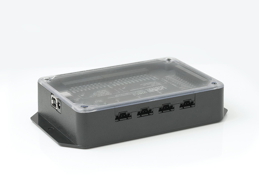
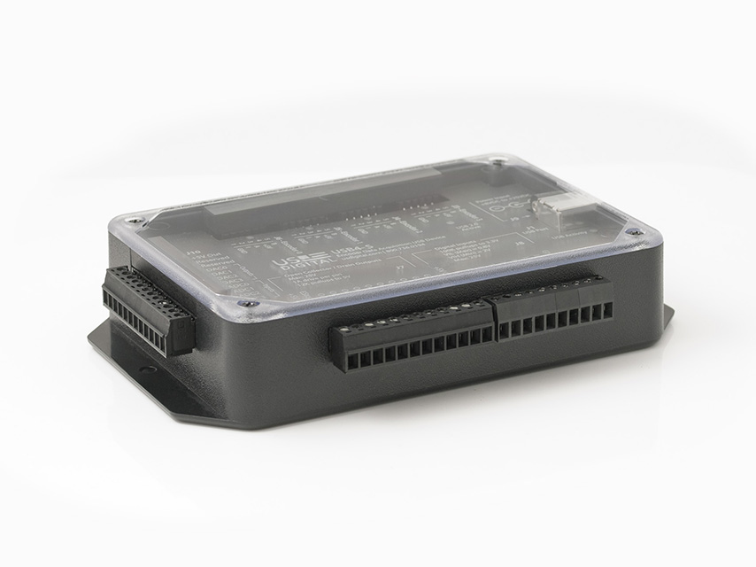
The USB4 is a data acquisition device designed to record data from 4 incremental encoders, 8 digital inputs, and 4 analog input channels. In addition, the USB4 provides 8 digital outputs and 4 analog output channels. The 8 digital outputs also have a latching emergency stop (E-Stop) input. When the E-Stop input is activated, the 8 digital outputs will turn off immediately. The analog input/output channels provide 12-bit data conversions at rates up to 44 kHz per channel. All communication between the USB4 and the host PC is sent over a USB interface. To handle continuous streaming of data over USB to the host PC, the USB4 has a 32 Mbyte FIFO buffer.
The digital input port can handle input logic levels from +3V to +25V, and the digital output port has open-drain MOSFET outputs to switch up to 1A at +25V. The range of the analog input/output channels is 0V to +5V. Four independent incremental encoder interfaces are implemented in hardware on the USB4. Each encoder channel has a 24-bit up/down counter that is easily reconfigured for various counting modes such as modulo-N, non-recycle, range-limit, and normal counter mode. You can select quadrature input modes of x1, x2, x4, clock/direction, and indexing modes. Each encoder channel can measure the pulse width and pulse period of its "A" input while simultaneously decoding the quadrature state. This feature allows RPM speed measurements to be made from the encoder input or interfacing to sensors with PWM (pulse width modulated) outputs.
The USB4 can capture data once per clock cycle of a user-programmable 32-bit clock generator or on every rising or falling edge of the input port pins. Data capture can be programmed to run continuously or to start only when certain conditions are met, such as the encoder count matching a certain value or if there is encoder movement in a certain direction. Encoder events can also output on the output port to trigger external devices. You can set trigger conditions for the analog input and PWM input channels; in addition, the USB4 can be configured to have the input port pins serve as a trigger to start data acquisition. The input port triggering allows the user to form the final trigger from a combination of conditions on the input port with up to 2 levels of triggering.
Software and documentation needed to use the USB4 are available on the US Digital website. A PC demo application allows the user to configure and explore various features of the USB4 using a graphical user interface. A library with a detailed Application Programming Interface is included so users can develop their own applications. US Digital provides several examples that demonstrate how to use the FIFO, log data, etc. For users that prefer lower-level control, a documented register-based interface is provided so you can configure the USB4's internal registers at the bit level.
Product Specifications
ENVIRONMENTAL
PARAMETER
MIN.
MAX.
UNITS
Operating Temperature
0
70
C
ELECTRICAL
Parameter
Value
Supply Voltage
8V to 25V
Digital Output Pins
Open drain voltage, 25V max.
Digital Input Pins
VIL(max) = 0.8V
Analog Output Range
12-bit DAC, 0V to 5V
Analog Input Range
12-bit ADC, 0V to 5V
Power consumption
115 mA @ 8 V, 77 mA @ 12 V or 42 mA @ 24V typical.
Max. current drawn from +5V outputs
550 mA (combined current of all +5V output terminals)
Max. encoder input frequency
5 MHz
Max. FIFO write speed (Time Based Triggering)
500 kHz
Max. FIFO write speed (Event Based Triggering)
Counter - 200 kHz, Input Port - 100 kHz
SINGLE ENDED ENCODER INPUTS
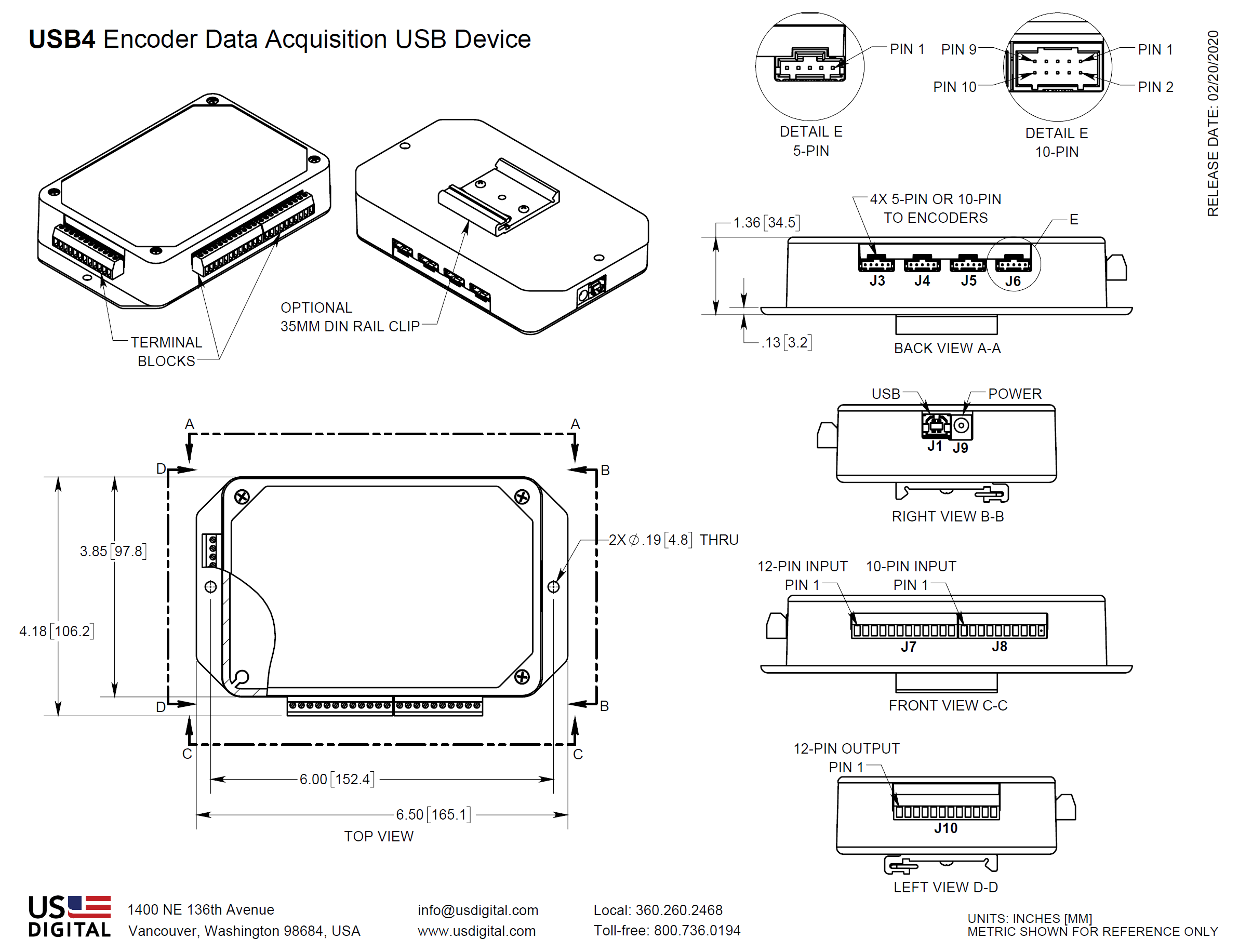
Encoder Channel 3,2,1,0 (J3, J4, J5, J6) Pin-out (USB4-S option):
PIN NUMBER DESCRIPTION
1
Ground
2
Index
3
A Channel
4
+5V out
5
B channel
Single Ended input circuit (internal to USB4):
DIFFERENTIAL ENCODER INPUTS
Encoder Channel 3,2,1,0 (J3, J4, J5, J6) Pin-out (USB4-D option):
PIN NUMBER DESCRIPTION
1
No connection
2
Ground
3
Index-
4
Index+
5
A- channel
6
A+ channel
7
+5V out
8
No connection
9
B- channel
10
B+ channel
Differential Input Circuit (internal to USB4):
DIGITAL INPUT PORT
J8 Pin-out:
PIN NUMBER DESCRIPTION
1
+5V power out
2
Din0 (LSB)
3
Din1
4
Din2
5
Din3
6
Din4
7
Din5
8
Din6
9
Din7 (MSB)
10
Ground
Input Port Circuit (internal to USB4):
DIGITAL OUTPUT PORT
J7 Pin-out:
PIN NUMBER DESCRIPTION
1
+5V out
2
E-Stop input (active low)
3
Dout0 (LSB)
4
Dout1
5
Dout2
6
Dout3
7
Dout4
8
Dout5
9
Dout6
10
Dout7 (MSB)
11
Ground
12
Ground
Output Port Circuit (internal to USB4):
Note: When driving inductive loads, add an external reversed biased diode in parallel with the load to protect the USB4 from damage caused by large voltage transients.
INTERFACE PORT
J10 Pin-out:
PIN NUMBER DESCRIPTION
1
+5V out
2
Reserved
3
Reserved
4
DAC0 (analog outputs)
5
DAC1
6
DAC2
7
DAC3
8
ADC0 (analog inputs)
9
ADC1
10
ADC2
11
ADC3
12
Ground
ADC Input Circuit (internal to USB4):
DAC Output Circuit:
PRODUCT CHANGE NOTIFICATIONS
Title
Date
Description
Download
PCN 4464 - CE - RoHS
6/30/2014
US Digital is aware of the increasing attention to world-wide environmental regulations, specifically with regard to the need for hazardous substance restrictions in electronic components and systems. As of July 10th, 2014 US Digital will now be CE Marking certain products inline with compliance under RoHS Directive (2011/65/EU). In order to achieve RoHS Compliance, the products will not contain more than the acceptable levels of the listed restricted substances within the RoHS 2011/65/EU directive.
Part Numbers Affected:
ED3
USB4
QSB
SEI-USB
MD2S
PS-5, PS-12, PS-24, PS-48 (Power Supplies)
PE
For the part numbers listed above, US Digital cannot confirm that they meet Low-Voltage and EMC Directives and for that reason US Digital cannot support shipping those products / product families into the CE required countries (For Example countries in the EU). Those products can still be shipped to Non-CE required countries with a Statement of Material Conformance to the RoHS Directive 2011/65/EU, in place of a RoHS Compliance Declaration.
Download
Additional Information
Product Notes
Cables and connectors are not included and must be ordered separately.
US Digital® warrants its products against defects in materials and workmanship for two years. See complete warranty for details.
User guides
Software
Related
3D Model Downloads
Please
configure your product first
to download a 3D model. (Note: The formats below will become links if there are 3D models available.)
SolidWorks Format
IGES Format
Parasolid Format
STEP Format
Datasheet
Feedback
US Digital's mission is a commitment to quality and constant improvement. If you find an error to a product on this page, please let us know !
Save Your Configuration
Easily keep track of your custom part numbers
What is this feature?
While configuring your encoder, you can save your custom part number at any stage. This helps you keep track of multiple configurations without needing to start over or write anything down.
How does it work?
Click “Add This Configuration to Your List” after selecting your options.
Your saved part number will appear in a mini list below the configurator.
The list is stored locally in your browser and persists across product pages.
Enter a quantity to view default pricing.
What can you do with saved configurations?
When you're ready, visit the Saved Configurations List page to:
Review all saved part numbers
Fill out a form to send your selections to US Digital Customer Service
Receive follow-up to complete your order or get support
Why use it?
Save time by avoiding repeated configurations
Compare multiple part numbers side-by-side
Simplify communication with our support team
Got it!