ED4 Product Description
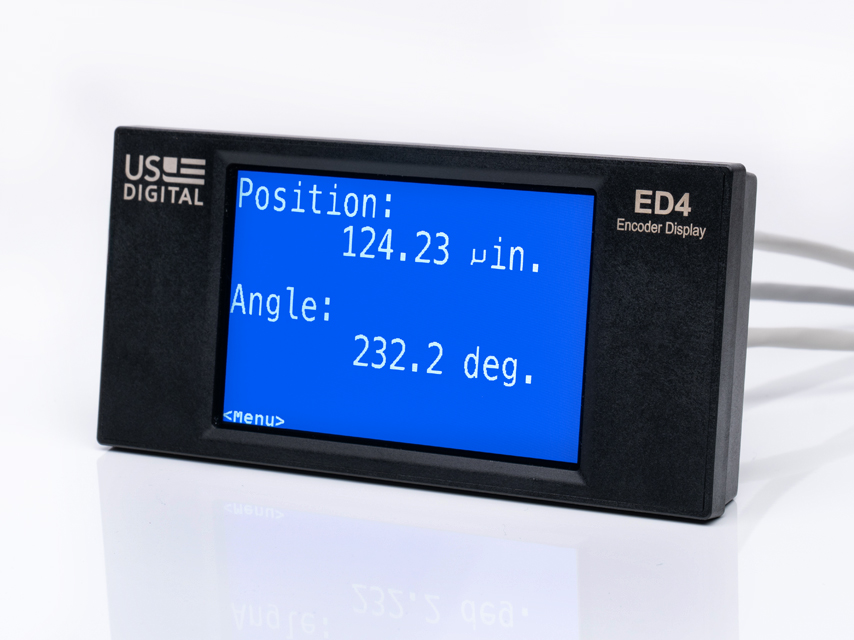
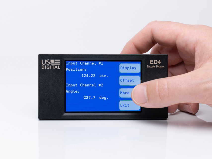
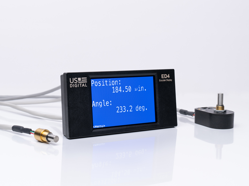
The ED4 is the next generation of US Digital's ED3 encoder display .
The ED4 can display:
Rotation speed or position of a quadrature output incremental encoder (single-ended or differential)
Absolute position of a PWM output encoder
Absolute position of an Analog output encoder
Programmable alarm conditions based on the encoder output values
The user configures the ED4 over USB 2.0 using a GUI application running on a PC. The software allows the user to customize the display features for a specific application. A programmable offset/scale factor and unit labels can be applied so the ED4 displays the position or speed in different units such as inches, meters/sec, degrees, etc. The ED4 stores its programmable parameters in non-volatile flash memory.
The ED4 is powered by the USB bus or by an external power supply of +7.5 to +28 VDC. The USB connection can also be used for firmware updates. The ED4 supports quadrature encoder input frequencies up to 3.75 MHz, allowing accurate measurement of high-speed motion.
Please note: A cable with a USB-B 2.0 connector is required to configure the ED4. This cable is not included and must be purchased separately from a third-party supplier.
Product Specifications
APPLICATIONS
Quadrature Counter, Tachometer
Quadrature encoder CPR tester
Up/Down Pulse Counter, Frequency Counter
Position or velocity display
Distance display
Digital level display
Speed zone alarm indicator
Programmable tilt switch
ENVIRONMENTAL
PARAMETER
VALUE
UNITS
Operating Temperature
-20 to 70
C
Electrostatic Discharge, IEC 61000-4-2
± 8
kV
Vibration (10Hz to 500Hz, sinusoidal)
10
G
Shock (11 milliseconds, half-sine)
50
G
OPERATIONAL PARAMETERS
PARAMETER
MIN.
MAX.
Encoder Name String Length
15 chars
Encoder Units String Length
7 chars
Encoder Value Display Range (including decimal fraction)
12 digits
Encoder Value Decimal Resolution
0
6 digits
Quadrature Count Range
-2^31
2^31 - 1
ELECTRICAL
PARAMETER
MIN.
TYP.
MAX.
UNITS
Supply Voltage, external (1)
7.5
12
28
V
Supply Current (2)
Encoder Supply Voltage Output (3)
4.75
5.0
5.25
V
Encoder Supply Current (each output)
150
mA
Digital Input Voltage
0
28
V
Digital Input Logic Low
0.4
V
Digital Input Logic High
2.3
V
Open-drain Output Voltage Range (4)
0
28
V
Open-drain Output Current
1
A
Open-drain FET resistance @ 1A
0.06
Ohms
Quadrature Encoder A/B or Step/Dir Frequency
0
3.75
MHz
Quadrature Speed Measurement Range (x4)
0.5
320k
Counts/Sec
Quadrature Speed Measurement Sample Period
0.1
2
Seconds
Speed Measurement Error
< 0.1%
Moving Average Speed Filter
0
15
Samples
Analog Encoder Input Voltage
0
5
V
Analog Encoder A/D resolution
12
bits
Analog Encoder Input Bandwidth
240
Hz
Anlog Encoder Source Impedance
50
Ohms
PWM Encoder Resolution (5)
16
bits
PWM Frequency
10
4000
Hz
PWM Encoder Input Voltage
0
28
V
Encoder Single-ended Interface
Encoder Differential Interface
(1) The ED4 can also be USB bus powered. An external supply is not needed in this case. If both USB and external power is connected, external power is used.
(2) Does not include current drawn by an external encoder.
(3) In Default mode, the 5V nominal encoder supply is generated from the 7-28V power supply voltage. In USB bus powered mode, the 5V nominal USB voltage powers the encoders directly. In HV Mode, the encoders are powered from the power supply voltage input.
(4) An external clamp diode should be used when switching inductive loads.
(5) PWM duty cycle is measured once per cycle. 16-bit resolution at 915Hz and below. 60000 count resolution at 1kHz, 15000 count resolution at 4kHz
OPERATING MODE
The ED4 is configured over a USB 2.0 interface using an easy-to-use PC application.The ED4 can display two encoder channels on its color LCD display. SIngle-ended/Differential Quadrature, Analog and PWM encoder outputs are supported. The encoder reading can be scaled and offset so the reading is in arbitrary units. The encoder name and display units are editable. The ED4 firmware is field upgradeable by the user over USB.ED4 Quick Start Guide for more information.
FACTORY DEFAULT CONFIGURATION
·
·
·
·
·
·
·
·
·
·
·
·
·
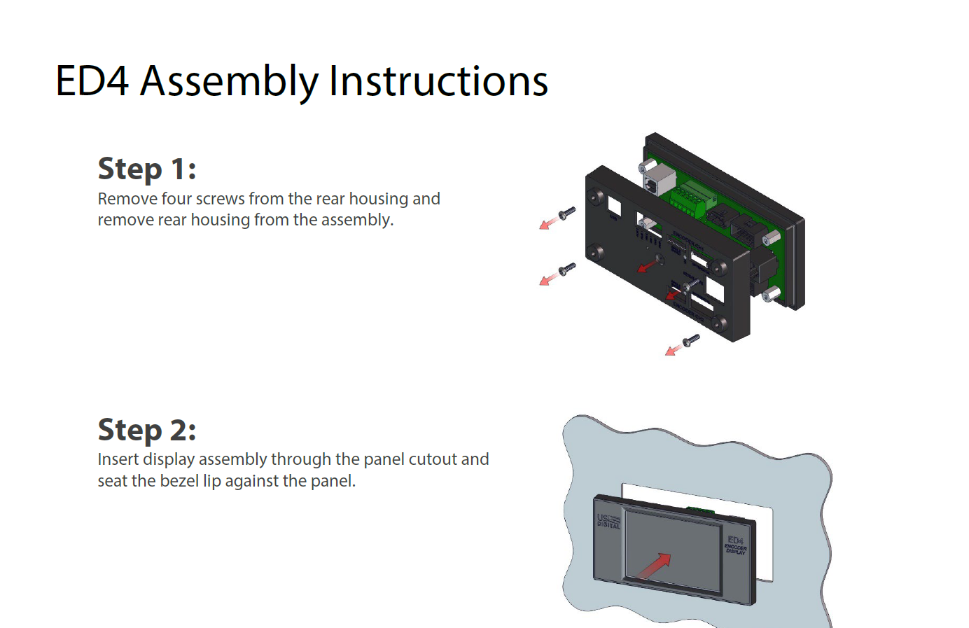
PANEL MOUNTING INSTRUCTIONS
Remove the rear cover by removing the four screws in the back.
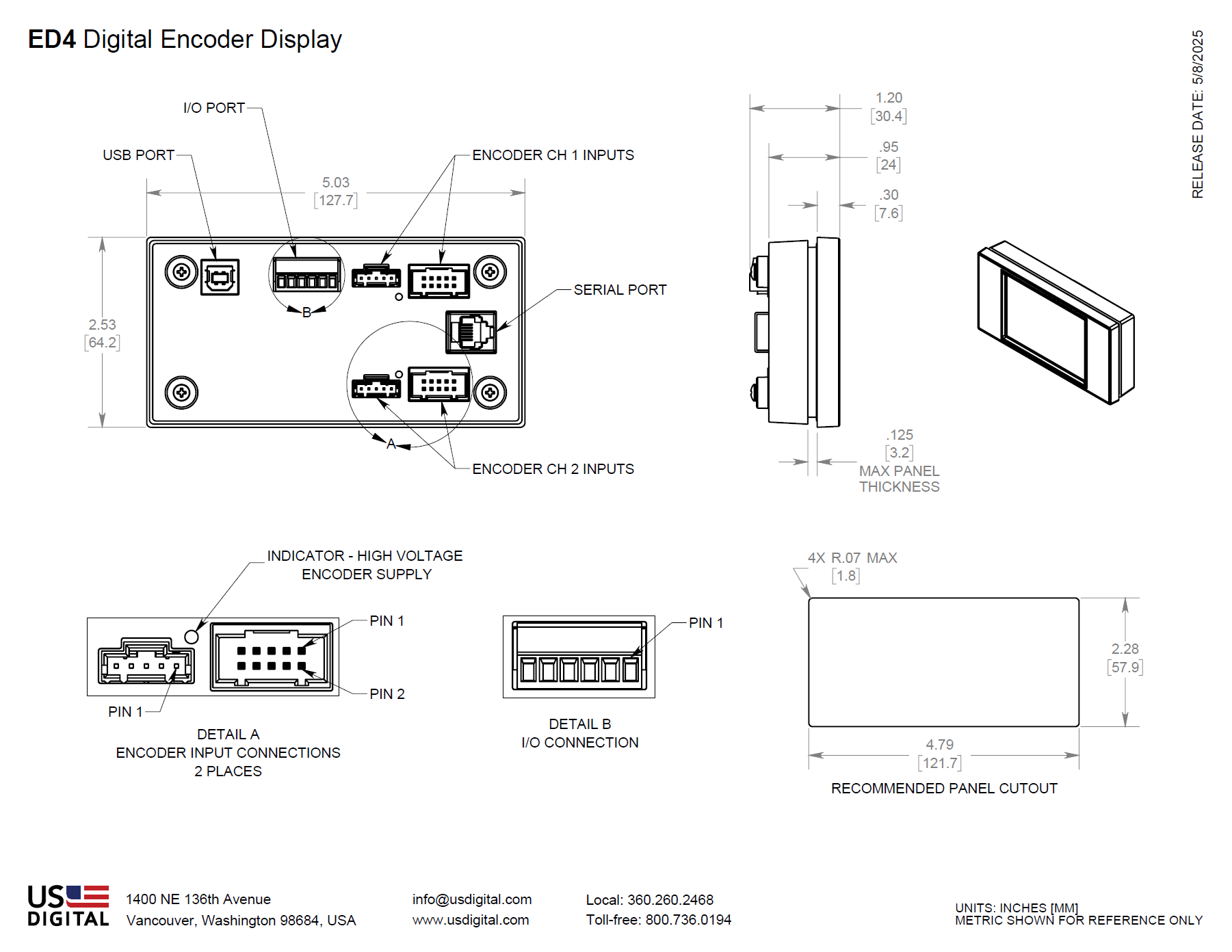
Insert the display through the rectangular opening in the front panel so that the gasket seals against the front.
Reassemble the rear cover to secure the display into the front panel.
The recommended mounting screw torque is 2 to 4 in-lbs.
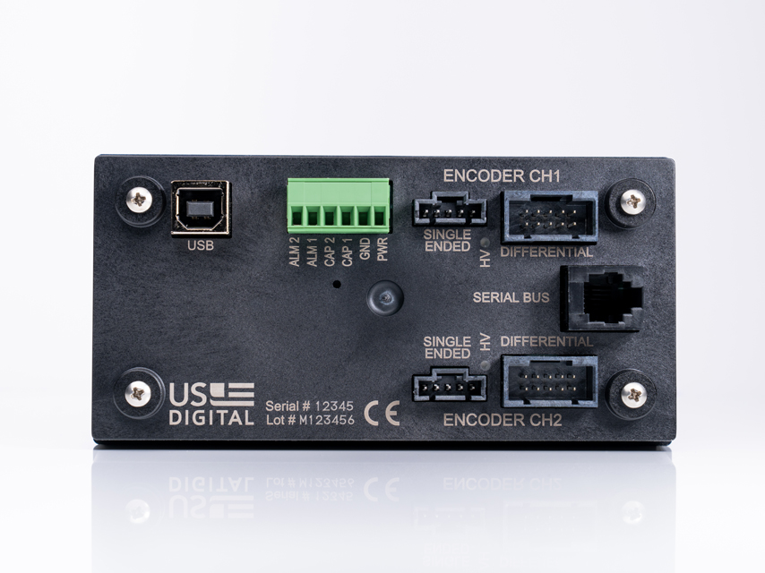
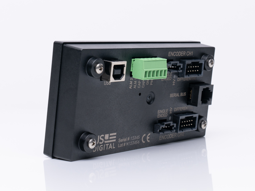
CONNECTOR PINOUTS
Encoder Channel 1/2 Connectors
PIN
5-PIN Analog
5-PIN PWM
5-PIN SINGLE-ENDED
10-PIN PWM
10-PIN DIFFERENTIAL
1
Ground
Ground
Ground
Ground
Ground
2
NC
NC
Index
Ground
Ground
3
Analog
PWM
A channel
NC
Index-
4
DC power out (1)
DC power out (1)
DC power out (1)
NC
Index+
5
NC
NC
B channel
PWM-
A- channel
6
PWM+
A+ channel
7
DC power out (1)
DC power out (1)
8
DC power out (1)
DC power out (1)
9
NC
B- channel
10
NC
B+ channel
(1) External DC power is output in HV mode, +5V out in standard mode
I/O Connector
PIN DESCRIPTION
1
External DC Power Input (7.5-28V)
2
GND
3
Channel 1 Quadrature Capture Input (Weak internal pullup, Falling edge triggered)
4
Channel 2 Quadrature Capture Input (Weak internal pullup, Falling edge triggered)
5
Channel 1 Alarm Output (Open Drain)
6
Channel 2 Alarm Output (Open Drain)
Additional Information
Product Notes
Cables and connectors are not included and must be ordered separately.
Power supply is not included
US Digital® warrants its products against defects in materials and workmanship for two years. See complete warranty for details.
Software
User Guides
3D Model Downloads
Please
configure your product first
to download a 3D model. (Note: The formats below will become links if there are 3D models available.)
SolidWorks Format
IGES Format
Parasolid Format
STEP Format
Datasheet
Feedback
US Digital's mission is a commitment to quality and constant improvement. If you find an error to a product on this page, please let us know !
Save Your Configuration
Easily keep track of your custom part numbers
What is this feature?
While configuring your encoder, you can save your custom part number at any stage. This helps you keep track of multiple configurations without needing to start over or write anything down.
How does it work?
Click “Add This Configuration to Your List” after selecting your options.
Your saved part number will appear in a mini list below the configurator.
The list is stored locally in your browser and persists across product pages.
Enter a quantity to view default pricing.
What can you do with saved configurations?
When you're ready, visit the Saved Configurations List page to:
Review all saved part numbers
Fill out a form to send your selections to US Digital Customer Service
Receive follow-up to complete your order or get support
Why use it?
Save time by avoiding repeated configurations
Compare multiple part numbers side-by-side
Simplify communication with our support team
Got it!